Our team is confident that you have highly qualified personnel with skills in the power supply industry, a good understanding of the inner workings of the PSU and an optimistic view of our innovative solutions. We have experience investigating your typical mistakes caused by traditional approaches to new products. As the General Designer of ALEXANDER ELECTRIC, I will try to tell you about the most “effective” mistakes.
You must understand that the most destructive thing for PSU is heat, due to the direct influence of temperature on reliability. The most important thing both you and we should strive for is to “spread” the heat centroids over the heat dissipating surface of the PSU, over its “soleplate” as much as possible! Miniaturization required for hardware, is a process aimed at reducing and thinning everything that lends itself to it.
As a result, the heat dissipating pad in our designs has a thickness up to 0.4 mm in the thinnest places of low power PSUs and up to 0.8-1.5 mm in high power PSUs. If you turn on the module without heat dissipation plate or heat sink, you can get the components temperature (transistors, diodes, suppressors, chips) at 150⁰С – 200⁰С, within 10 seconds! If you manage to turn off the module quickly, it does not mean that fate will forgive you another such attempt.
Be warned: a plastic fan is no help to you there, even if you put it in a cardboard tube for efficiency.
TIP: Follow the datasheet carefully, don’t run the PSU on an office desk without a heat dissipation plate to simulate heat sink.
If you have a heat sink, you are in for some common mistakes:
If you need to turn on the unit for a short time, e.g. for input inspection, a 4-8mm copper plate should be used as a temporary heat sink. The width and length of the plate should be in 1.5-2 times the size of the unit itself.
Do not solder wires to the pins of the DC/DC PSU type! All DC/DC PSUs with pins are designed to be mounted on printed circuit boards only!
When soldering a wire, especially a large diameter, and when unit is operating in a vibration and shock environment, and even during assembly, the unit pin is a cantilever that transmits the force to the PCB inside the PSU, both during soldering and long term in operation. And, combined with heating, micro-movements give rise to forces on the ceramic capacitors inside the PSU that split the ultra-thin layers of ceramics.
Explosions and PCB burnouts in these areas are inevitable.
Filling compound, even very stiff, does not help here and can add to the trouble on thermal cycles.
TIP: If you have difficulty designing a part of the PCB for a PSU, we can do it for you for free. The best way to connect the PSU pins in your equipment is to use PCBs with at least four layers of 100 – 400 µm foil. We can supply these printed circuit boards to order. We can also provide pre-design and simulating the cooling system.
The customer’s top errors include a very interesting point – how to measure ripple at the output of the PSU correctly?
We RECOMMEND:
All of the above is quite difficult, but otherwise you will measure not the true pulsations of the PSU, but the artifacts in the OSRC cable, caused by the resonances of the cable and connection scheme!
In our opinion, it is better to use special OSCs with differential input and at least special cables for measuring exactly the pulsations of pulsed power supplies.
AC/DC PSUs have all the necessary elements in their composition for matching with typical electronic and electrical circuits and usually do not require additional components on the input and output.
However, it should be borne in mind that the input fuse they contain is only intended for fire-fighting functions, i.e. it is designed to withstand a considerable excess of input current caused by a major malfunction in the module itself.
This fuse is irreplaceable, the module itself in such an accident also suffers a number of damages and is not repairable. For example, due to external influences the varistors can fail (in case of emergency overvoltage of the mains), the semiconductor suppressors, the printed circuits on the board are damaged, etc.
In this regard, for safety reasons, it is mandatory for AC/DC modules to include a hardware type fast-acting fuse, replaceable type (or a fast-acting circuit breaker) and, most importantly, with a triggering current that will not lead to fires in the module structure.
The fuse as well as the mains protection circuit breaker is selected by the condition: I = (2…2.5)xP of the module on the label, divided by Uin.min.
For example, the JETA2400 module must be connected in equipment with a minimum line voltage of 100V through a 2×2400/100 = (50…70A) fuse.
In critical cases to reduce disturbances in the input and output conductors, ferrite cores with high magnetic permeability (5 000 – 10 000), dressed on the input and output conductors, are effective, so that inductances of the common type are obtained.
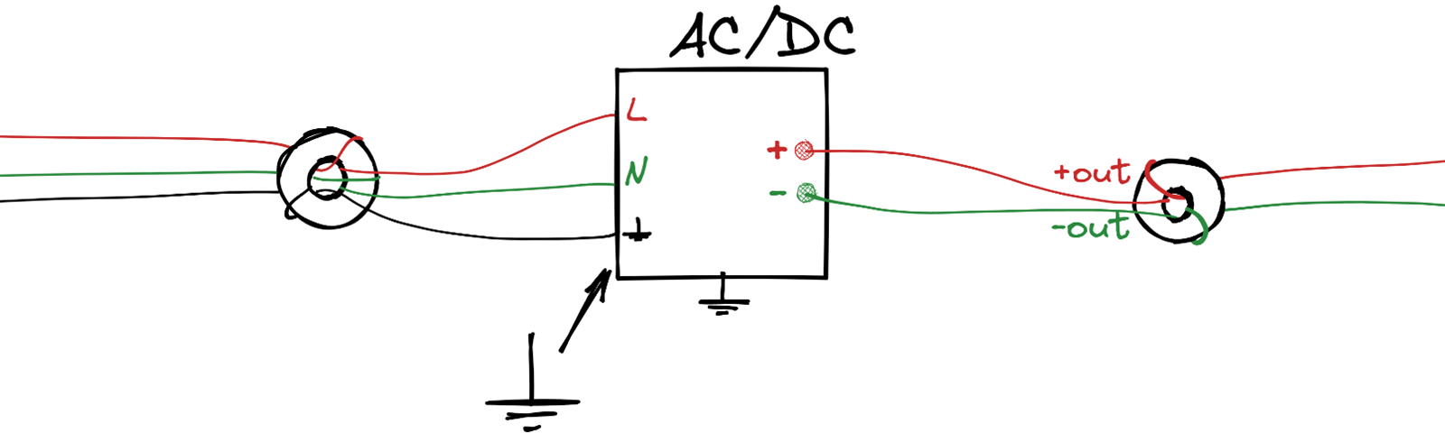
This is shown schematically in picture above. Usually, one or two turns are required. But the most effective solution to improve the EMC parameters is to use the interference filters in this catalog.
But there are differences in case of DC/DC type modules. Small dimensions and high-power density do not allow in some cases to place all protective and interference-suppressing elements in the module design.
Also, such modules have a pronounced negative input impedance, which often leads to failure of their stability. Therefore, we recommend connecting electrolytic and ceramic capacitors of different types to the input pins (consult us).
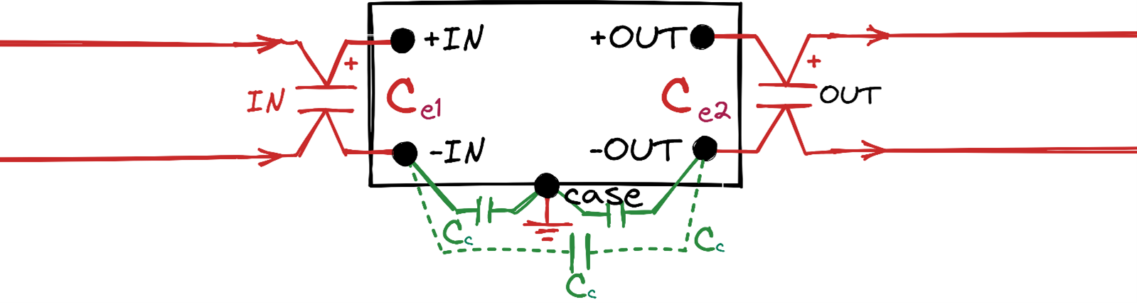
Further in picture below we show a minimum connection diagram, i.e. the DC/DC module must not be switched on without the external elements shown in the diagram!
The input and output points (pins), the module case as a rectangle and the case pin as ground are shown conventionally. The components shown in the picture – electrolytic and ceramic capacitors are connected in a very short way to the corresponding case pins, case is grounded by the shortest possible route.
Ceramic capacitors with capacity 10 – 20 nF are chosen of temperature group X7R at operating input voltages up to 50 V, at higher voltages, e.g. 100…200 V they are chosen with capacity 3 – 6 nF.
Electrolytic capacitors (aluminum, polymer aluminum, polymer tantalum), are placed in close proximity to the corresponding pins. In this case, their internal ohmic resistance is used to damp high-frequency resonance oscillations.
Their operating voltage should be at least 1.5 times the maximum voltage applied to them, any foreseeable surges, even of microsecond duration, should be taken into account when selecting capacitors.
In special cases, if there are circuits with commutated inductances near the module (e.g. relays, chokes, transformers, electric motors, etc., which can cause pulse interference in the conductors connected to the module – it is desirable to have semiconductor suppressors on the input and output leads of the module (not shown in the figure).
It is highly desirable (!) that the printed conductors connecting capacitors to pins do not get into the projection area of the module’s case (go under the case as little as possible).
It is also desirable to place a shielding surface on the printed circuit board, connected to the ground pin, under the module in the case projection. It is not permissible to run signal conductors in this area.
An approximate calculation of the capacitance of the input electrolytic capacitors to ensure stable operation of the DC/DC type module is as follows.
Imagine that the minimum input voltage at the outputs of the module is 9 V, the output power of the module is 100 W. In that case, you would need an electrolytic capacitor directly on the input pins with a capacity greater than 250 µF, or a capacity greater than 100 µF for every 100 W of power for a mains with a minimum input voltage of 16 V. Considering that the capacitance can be reduced by about 2.5-3 times if the voltage is increased by a factor of 2, we give an approximate table for the selection of DC/DC input electrolytic capacitors for our “28”, “28W”, “48W”, “150” and “270” mains.
| Mains | «48W» | «28», «28W» | «48» | «150» | «270» |
| Input capacitance per 100 W | 6×47…8×47 µF or 3х100…4×100 µF 100V e.g., UBW NICHICON | 3×47…4×47 µF or 2х100…3×100 µF 100V e.g.,UBW NICHICON
| 3×22…4×22 µF or 2х47…3×47 µF 160V e.g.,UBX NICHICON | 3×6,8…4×6,8 µF or 2×10…3×10 µF 350V e.g.,UBX NICHICON | 2×15…3×15 µF or 2×18…3×18 µF 500V e.g.,UСY NICHICON |
We remind you that the best solution to reduce the level of interference is to use in addition to the considered filters of our production listed in this catalog.
Best regards, general designer of ALEXANDER ELECTRIC
Alexander Goncharov

